Introduction
This project aims to provide a hands-on training/tutorial for begginers into IoT hacking. I myself gained a great deal in knowledge by doing things, instead of just reading articles online, so if you can, then try replicate these techniques on old hardware. Make sure you don’t need them, before starting to work on them.
I had this old router laying around, so I decided to try my hand at finding some vulnerabilities, exploiting them, and maybe even giving the router a new purpose, instead of just using it for target practice.
Information Gathering
Sources of information
- Online resources
- Manufacturer’s website
- FCC
- Blogs
- Photos
- Backside of the router
- Take it apart
- Pinouts of ICs
- Console Output
- Firmware extraction
- Manufacturer’s website
- Blogs
- Manual SPI flash extraction
Gathering Phase
Online resources
- Can download firmware of the device
- Can establish a path towards the vulnerabilities patched through updates
- Default login users and password of web user interface “admin” and blank
- Can gain info about the performance of the device
- Can see the insides before taking it apart
- Details of FCC and IC IDs
- Flash and RAM of the hardware version revision B5
- Exposed 4-pin serial hardware interface
- Default login users and password of web user interface “admin” and blank password
Photos
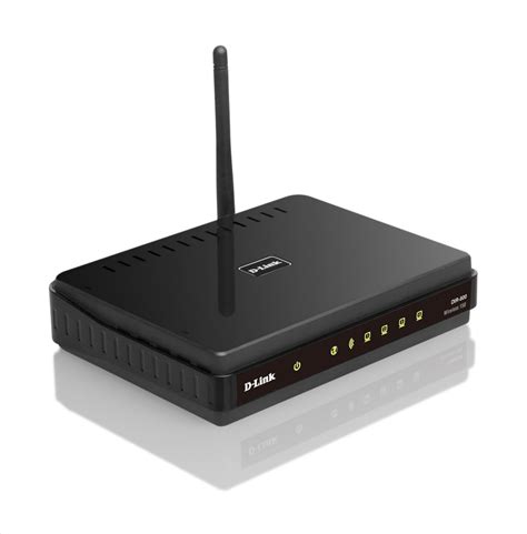
External photos can be really helpful, since most routers have information printed on the back, regarding default user and password, the IP address of the router and such.
This router has additionally printed on it’s back the hardware version, which is H/W revision B5, the firmware revision F/W v2.10, serial number and MAC address. The FCC and IC IDs are also helpfully printed, so we could use this to search for it online first.
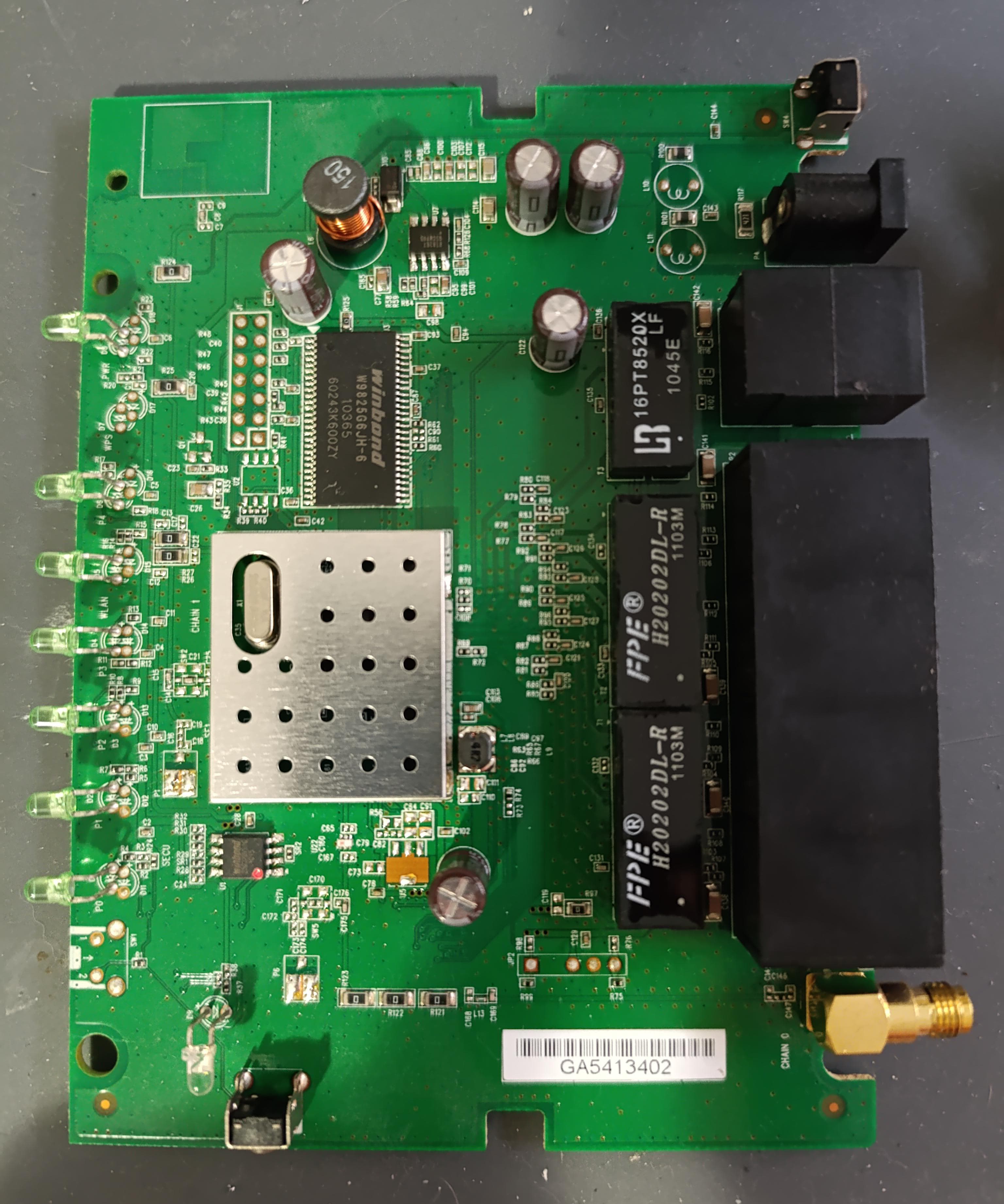
Internal photos are also really important, since we can establish vectors of attack on the exposed interfaces. Also, we can double-check the information read on the online resources.
Pinouts of ICs
As we can see from the photos and online resources, the ICs used are the following:
| Component | Manufacturer | Image | Datasheet Link |
|---|---|---|---|
| RT5350 SoC | Ralink |  |
Datasheet |
| W25Q32BV SPI Flash | Winbond |  |
Datasheet |
| W9825G6JH SDRAM | Winbond |  |
Datasheet |
| RT8267 Step-Down Converter | Richtek |  |
Datasheet |
We were lucky that the online resources told us the CPU, as an EMI shield is soldered on top of the CPU. The CPU uses MIPS architecture, and it’s a specialized SoC that is used in embedded devices, such as cameras, routers and other Internet-enabled appliances.
The SPI flash is a common 4MB chip, most cheap routers include only a 4MB capacity IC, while the RAM chip has 32MB capacity to hold the uncompressed firmware and rules at runtime.
The last IC is just a step-down converter, meaning the 5V that enter the power jack are brought down to a value adjusted from this IC. This is not that important right now, but could be if you wanted to feed another voltage (lower) directly to the CPU.
Console output
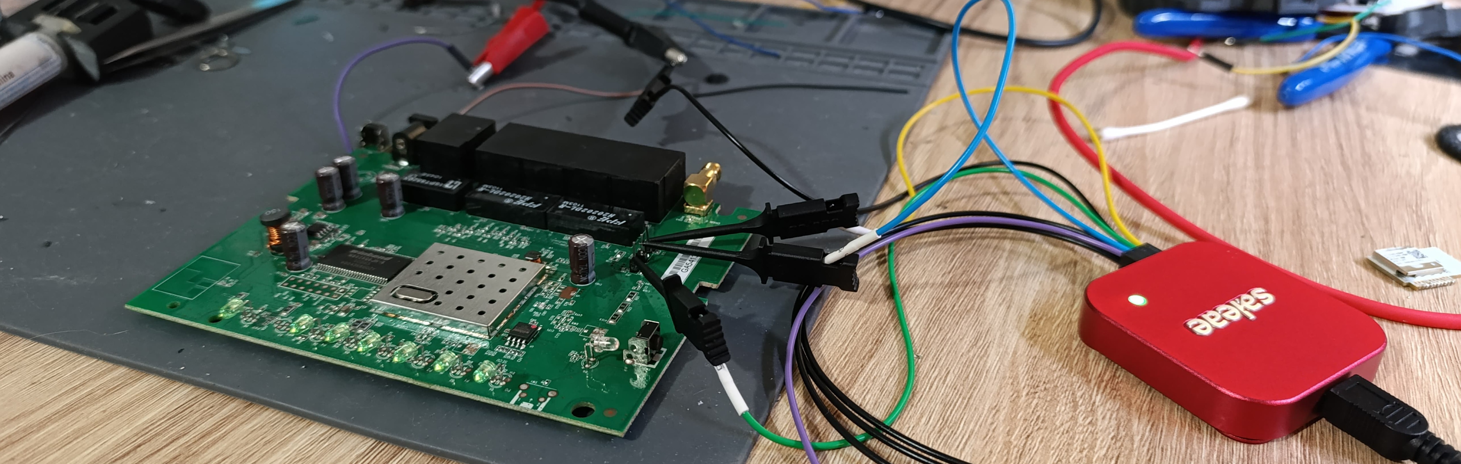
To get to the serial console, we must first find it and hope it is enabled. Luckily, we know from the online sources that it is available. We must first attach pins to the bottom interface, and then sniff which one is the receiving line and transmitting line. We can do this by using an oscilloscope, but a logic analyzer is more appropriate, since these signals are digital.
A good analyzer which I recommend is the Logic 8 Analyzer.

After soldering some pins to the 3 through-hole pins (as a fourth one is a GND pad), we can see that the first from the top to the bottom is the transmitting line of the router, the second one is the receiving line, and the last pin is VCC. The protocol used is UART serial and is running at 57600 baudrate, the software detected it and automatically adjusted.
The full dump of this can be found in the github repo.
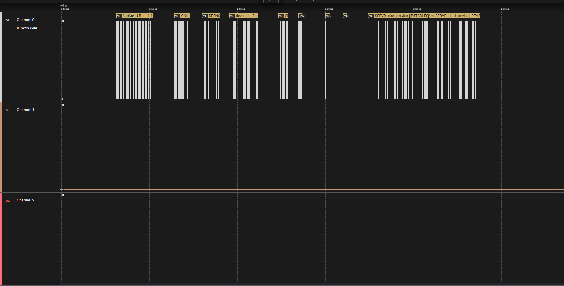
 Some things we can observe are:
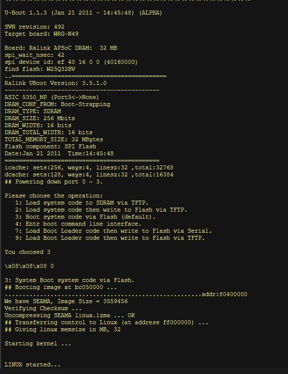
- The bootloader is U-Boot 1.1.3 (Jan 21 2011 - 14:45:48) (ALPHA)
- The router lists the board as “Target board: WRG-N49”
- We can use 6 operations when booting:
- 1: Load system code to SDRAM via TFTP.
- 2: Load system code then write to Flash via TFTP.
- 3: Boot system code via Flash (default).
- 4: Entr boot command line interface.
- 7: Load Boot Loader code then write to Flash via Serial.
- 9: Load Boot Loader code then write to Flash via TFTP.
- Also, the operation chosen is 3)
- Linux version 2.6.33.2
- GCC version 4.3.3
- “VFS: Mounted root (squashfs filesystem) readonly on device 31:1”
- Uses BusyBox v1.14.1
- Some other networking tasks and events are logged
Manual SPI flash extraction
Extracting the flash memory of a target device can be done by manipulating the previously-found flash memory. The target flash has as protocol SPI. You can get away by using a cheap Arduino to extract the memory and then writing it on the PC for analysis.
While this can be done on a tight budget, it won’t give you neither speed nor flexibility for some types of memory. I used the XGecu T48 Flash Programmer for this job, as it supports lots of memory ICs and also microcontrollers.

I wired it using a clip-on to the flash, and dumped the contents on the disk. Not disconnecting the flash from the SoC can have consequences, as the SoC could receive power from the flash and try to run, so if this happens, desolder it first. This didn’t happen with my router.
Firmware inspection incoming.
Firmware Analysis
Some tips before starting to analyze the firmware can be found on Hacktricks.
Bird’s eye-view
In this phase, the firmware is a single 4MB file, that’s ready to be decompressed properly. We can firstly analyze it using binvis.io.
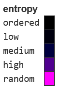
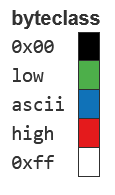
The term byte class refers to a classification system used to categorize individual bytes of a binary file based on their value, while entropy refers to a measure of the “randomness”or “uncertainty” in data.
This means that we can visualize where the human-readable data could be and where compressed or encrypted is found.


After this visual inspection, it is more clear how this memory was split. Some ASCII data is found in the blue spaces, while the other data is more random. To get more details we can use binwalk.
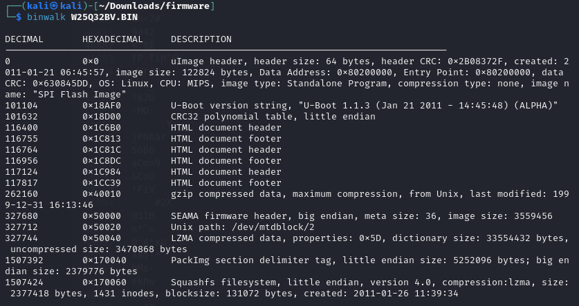 We can see at which offsets the signatures of different file types was found. The blue spaces we saw earlier where the HTML files and U-Boot strings.
With binwalk we can also extract the data found with those signatures. The command to extract it, and also make it recursively is binwalk -eM. The extra arguments are “extract” and “Matryoshka”, meaning we extract recursively if we find more compressed files.
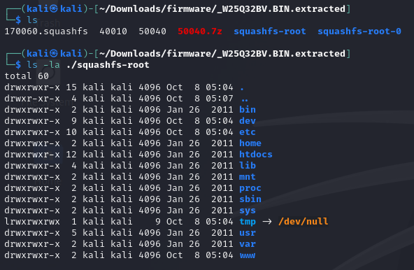
The file system is found under squashfs-root, which is a compressed read-only file system that’s commonly found on these types of embedded devices. As we can see, it is compressed with LZMA.
When the device boots, the CPU loads the squash file system into RAM, providing redundancy with the read-only parameter.
I attached the firmware image in the GitHub repo.
Digging into the files
After revealing the files, we can get to work on analyzing the system and it’s files. We have 2 files that can be analyzed, not counting the file system. The first one is called “40010” and it’s full of HTML. The second is “50040”, and it’s a binary.
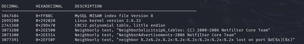 Performing an analysis again, with
 binwalk, we can see that it contains a MySQL file, some Netfilter iptables data, Linux kernel version and checksums. Knowing that the squash-fs is kept on read-only, this could be the zone of memory that the SoC writes it’s rules, that can be modified at runtime and loaded at boot-time.
After trying to use the MySQL file, I searched the exact header description and found this Reddit thread, which says that, while binwalk detects a file, it may be a false positive caused by a short file signature inside the target file.
Using strings inside this file can be helpful, since we can see what’s going on inside the file. I found this string when searching:
console=ttyS1,57600n8 root=/dev/mtdblock1 noinitrd,
that looks like a console connection on interface ttyS1 at 57600 baudrate. This double-checks the connection we established earlier.
Going deeper in the /bin folder, we can see some binaries, along with the boot-time mentioned, busybox. We know that it’s 1.14.1, but double checking again with strings reveals some interesting program names, along with the busybox’s version.
BusyBox is an open source program that combines tiny versions of many common UNIX utilities inside it. Meaning, if we cannot find a linux binary that we need, we could try invoking busybox <binary_name, as stated in the documentation of BusyBox:
/bin/busybox ls
The version used in our device is 1.14.1, but it’s from Anno Domini 2011, while the OG 1.14.1 dates back to 2009. This may differ because the architecture of the router is MIPS, meaning it must be cross-compiled by a developer from source to the target MIPS-32 architecture of the Ralink SoC. That could be the explanation for the time difference.
We can go deep inside the rabbit hole with BusyBox, we could even try to develop our own exploit by decompiling it with Ghidra (as I tried to), but it’s simpler to list all the available commands from BusyBox and then searching for vulnerabilities individually.
These are the utilities that can be found in this build:
[, [[, basename, bunzip2, bzcat, bzip2, cat, chmod, cp, cut, date,
        echo, egrep, expr, false, fgrep, free, grep, gunzip, gzip, hostname,
        ifconfig, init, insmod, ip, ipaddr, iplink, iproute, iprule, iptunnel,
        kill, killall, killall5, ln, ls, lsmod, mkdir, mknod, modprobe, mount,
        msh, mv, netstat, ping, ping6, ps, pwd, rm, rmmod, route, sed, sh,
        sleep, sysctl, tar, test, top, touch, tr, true, tunctl, umount, uname,
        uptime, vconfig, wc, yes, zcat
We could try searching GTFOBins or LOLBAS for some exploitable binaries, but first we need to have console access for these to work, remote or physical. Let’s try accessing it from the console interface.
Using an FTDI FT232, you can connect to the UART interface, and access the console.
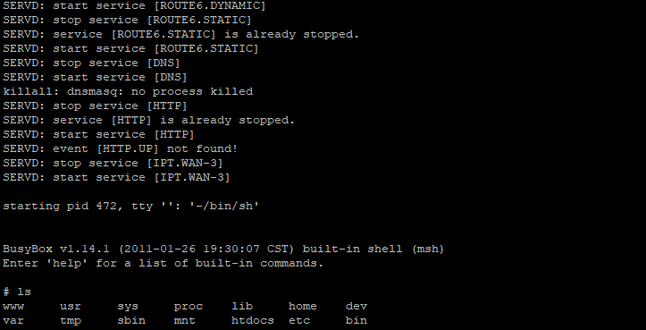
No password needed, no means of authentication, just straight root permission to do what you want (with what you have available). The BusyBox utilitary and shell commands don’t help us, but digging into the /usr/sbin we can find multiple interesting binaries that can help us download or interface with the Internet directly, since no wget curl or nc exists in the busybox binary:
xmldbc             sendmail           mfc                httpc
xmldb              seama              login              hostapd
wps                scut               logger             hnap
widget             rt3052esw          logd               gpiod
wfanotify          rndimage           llmnresp           genuuid
vconfig            rgbin              lld2d              fwupdater
usockc             rdisc6             klogd              fonts
updatewifistats    radvdump           iwpriv             event
updateleases       radvd              iwconfig           ecmh
udhcpd             psts               ipv6pdip           dnsmasq
udhcpc             proxyd             ipv6ip             dhcp6s
ubcfg              pppd               iptables-save      dhcp6c
trigger            portt              iptables-restore   devdata
telnetd            pidmon             iptables-multi     devconf
tcprequest         phpsh              iptables           ddnsd
tc                 phpcgi             ip6tables-save     ctest
susockc            pfile              ip6tables-restore  brctl
smtpclient         ntpclient          ip6tables-multi    ated
slinktype          nsbbox             ip6tables
service            netbios            ip
servd              neaps              igmpproxy
telnetd- telnet server - useful for uploading and then executing cross-compiled softwarehttpc- could be linked to HTTP client, but remains to bee seenusockc/susockc- couldn’t find something relevant on the Internet, but has “sock” in the name, so this could work
Exploitation
Remote code execution
As we already have root on the console, with no password, an environment must be setup for making the code execution easier, without using a TTL converter. Such a technique would be remote code execution, where we somehow get the same root shell, but remotely.
The utilities we searched for in the last section are helpful, because we cannot write our own code and compile it (no gcc compiler available). We cross-compile some code on the target MIPS 32 architecture, transfer it on the router then run it to get remote shell and also find a way to persist the backdoor through a power cycle.
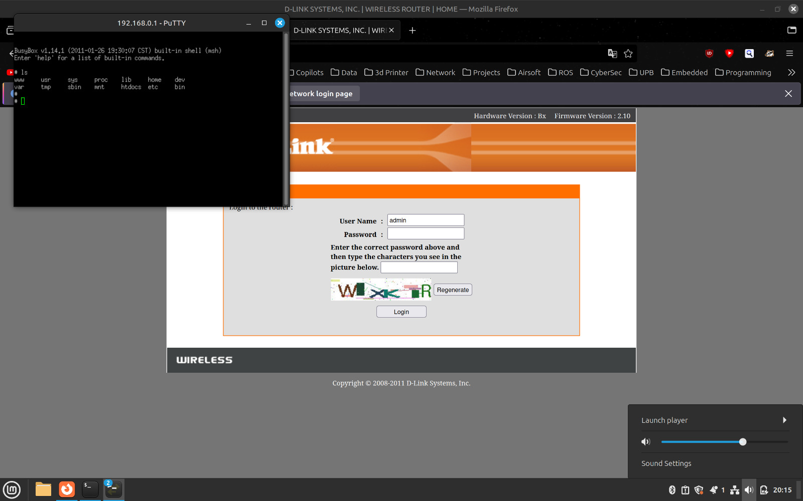
telnetd is the first binary found that could be used to achieve this.
I got it working on port 2020 and connected through Putty.
Payload crafting
There are lots of methods to get RCE up and going, but to keep it simple we can either compile a program, like nc, on a Linux machine to the target architecture and transfer it or find out if we can use a socket binary so we can bypass building on this arcane architecture. We can transfer the binary with Telnet on the router and find a way to execute it every time we boot it, to achieve persistence.
We know the target router uses MIPS32 and has Linux 2.6. Let’s see how binaries are compiled and ran from the squash-fs partition to get a glimpse how our binaries must be compiled:
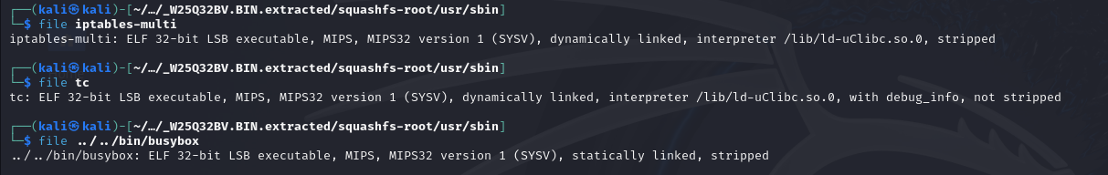 As we can see, the programs are compiled as 32-bit ELF LSB executables, they have MIPS32 v1. The ones in
 /usr/sbin/ are dynamically linked and also use uClibc as interpreter, which is “a C library for developing embedded Linux systems”.
Let’s just not go further the rabbit hole, but one of usockc or susockc should work to transfer data (our RCE commands) over the network, from our PC to the router.
Toying with the GPIO
The general purpose input-output on this router are linked to things like buttons or LEDs. When an event happens, a handler actions the GPIO on the SoC to do something. For example, in the case of WiFi not working, a LED might be yellow. This means that an event is driven to the pin of that specific LED.
Let’s see if we can see where it’s used and how, to give us a chance in writing our own code to manipulate it, by starting a simple recursive search:
egrep -IR "gpio"
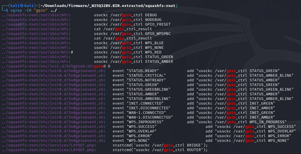 This is a snippet from the
 /usr/sbin/mfc script:
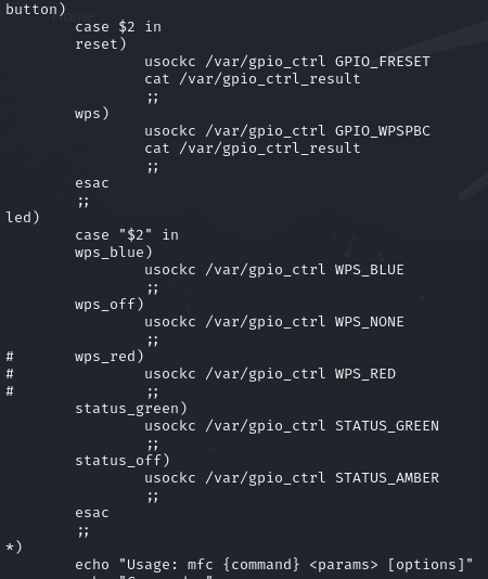
As we can see, there are some scripts which use the word “gpio”. gpio_ctrl seems to be the binary that is executed with a parameter, such as STATUS_GREEN, and it’s launched by usockc. usockc is the binary that we found earlier, and by taking a closer look with Ghidra it looks like it starts and then manages a socket:
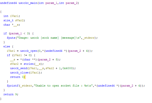 Having analyzed this, we thought wrong of
 gpio_ctrl, as we can see now it’s just a named socket.
The /var/gpio_ctrl/ socket isn’t available in the flash memory, so it must be available when the system is running uncompressed into the RAM. Digging into the firmware for the program that launches gpio_ctrl we find /usr/sbin/gpiod that starts it.
The flow for gpiod is that it starts the registers and manages the socket communication. We don’t really need to know more, as we can manipulate a script just like mfc which could start a socket with usockc and push some commands to the gpiod GPIO driver.
This is the script that I used to make the WPS LED blink on and off at 1Hz:
#!/bin/sh
while true; do
    mfc led wps_blue
    sleep 1
    mfc led wps_off
    sleep 1
done
This is how it behaves:
Further customization
This walkthorugh has lots and lots of different ways to exploit and customize the router. You can use any method from here or that's not explored to achieve your goal, since this is the purpose of hacking: finding creative ways to achieve something.
These are some further things to explore if someone has the time:
- Try to cross-compile a binary and upload it to the router
- Explore the suspiciously looking JTAG 12-pin interface on the PCB
- Reverse engineer the pinouts from the SoC to the pads to drive even more pins
- Get GCC up and running to compile on the device
- Compile, run and play Doom