Reusing the rangefinder
The next step in this project is to reuse the gadget in our own works, as this is what we aimed for. A problem could be the fact that we need the keyboard PCB connected to be able to short the pins to 3.3V or to GND.
If you would just want the laser module, that would be a problem, as you’d first need to reverse engineer the ribbon cable pins, then solder them to an appropriate ribbon cable terminated to bigger wires, or just solder them directly to the board/connector. Also, you’d need to provide a power board to power it, so that’s an excuse on being lazy.
Adapting to UART
Adapting this rangefinder to UART can be done by having a secondary microcontroller being an intermediary between the 2 end devices. We can keep it simple and use and Arduino as an I2C slave, process the bytes of data and correlate them to the measured distances, and give the control to the end device talking to it on the UART interface. A sample code can be found on Arduino’s example library of I2C:
#include <Wire.h>

void setup(){
  Wire.begin(0x3F);
  Wire.onReceive(receiveEvent);
  Serial.begin(9600);
}

void loop(){
  delay(10);
}

void receiveEvent(int howMany){
  while(1 < Wire.available()){
    char c = Wire.read();
    Serial.print(c);
  }
  int x = Wire.read();
  Serial.println(x);
}
This code can be adapted to listen to the address of 0x3F and then convert the I2C packets to floating numbers, which can be sent over the UART interface. Also, We can use the digital outputs of the Arduino to pull LOW or HIGH the rangefinder to measure or turn it on and off.
Do not forget that most Arduinos (UNO, Nano) work at 5V logic level, so you don’t want to pull the line HIGH directly, because you’ll be pushing 5V on a line that expects 3.3V, it’s not be going to be fun for the device. You need to use a level shifter for the I2C also, and if you get a 4 channel one, you can wire that up to the HIGH also.
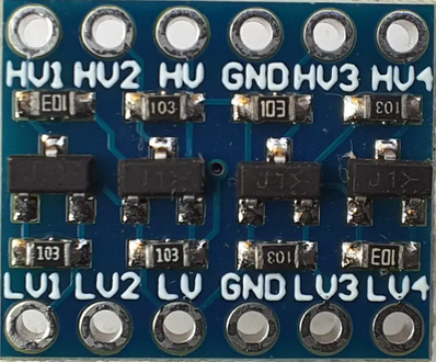
The “LV” - Low Voltage is connected to 3.3V and “HV” - High Voltage is connected to 5V and the GND should be common. After that, the Arduino IO will be wired to HV and the rangefinder’s IO to LV. I tried using an Arduino Uno, but I didn’t manage to capture all the packets of the I2C communication, even at 400kHz frequency. After that, I tried using the code above, but with a Raspberry Pi Pico, and it worked, just like that. 4 hours for trying to debug a thing, when I could’ve tried the Raspberry Pi Pico. Maybe it’s from the speed of the microcontroller, since it’s almost 10 times faster than the ATMega256 that the Uno uses.
The neat part about the Pico is that I don’t even need to convert the code from Arduino C++ to something else, thanks to Earle F. Philhower, who made RP2040 code for the Arduino Core.
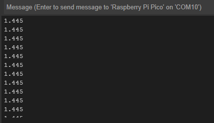
After wiring up the pico to the rangefinder, we can see that the microcontroller can indeed understand the rangefinder. We now need to make the code to press the keyboard buttons. This should be easy, as the keyboard is not consuming a lot of current, we can drive it low or high directly from the pins of the Pico, and since it’s using a 3.3V logic, we don’t need logic level shifters.
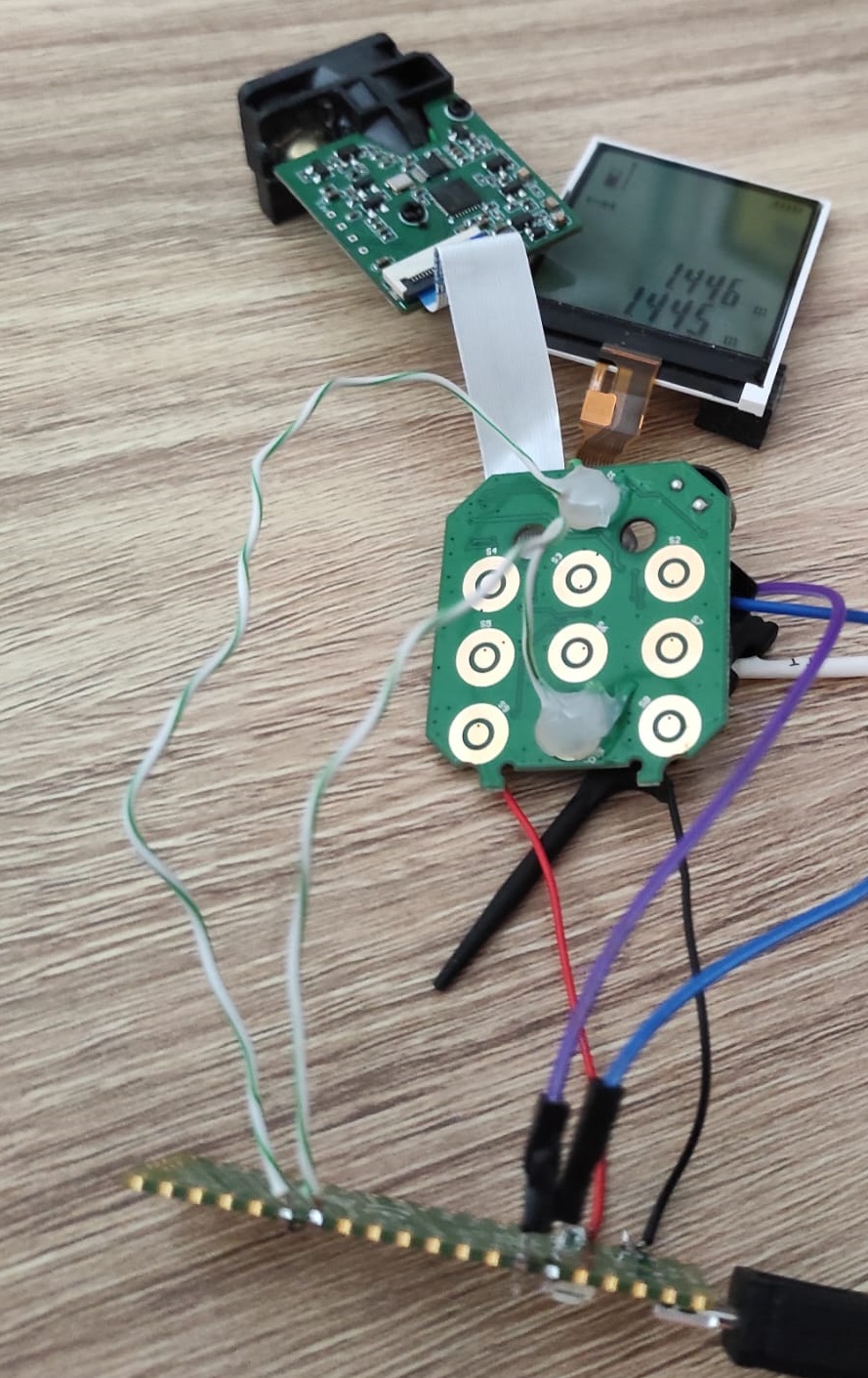
This is the physical setup, with the measurement and power pins directly wired to the keyboard.
I provided the code on this repo, but, remember, use only 3.3V if not using logic level converters, otherwise the magic smoke might escape from your devices.