Analyzing I2C Packets
After correctly stating that I2C data flows from the microcontroller, we must now understand how it works. The microcontroller would be an I2C master, and the screen (because it’s connected directly to the I2C line) is the slave. The keyboard is not an I2C device, as through many tries, there is no specific data to/from this device.
The screen’s address is 0x3F in hexadecimal or 63 in decimal, and the microcontroller’s address is 0x18 hex and 24 decimal. While capturing some data, after measuring once, there are lots of packets going through the data line.
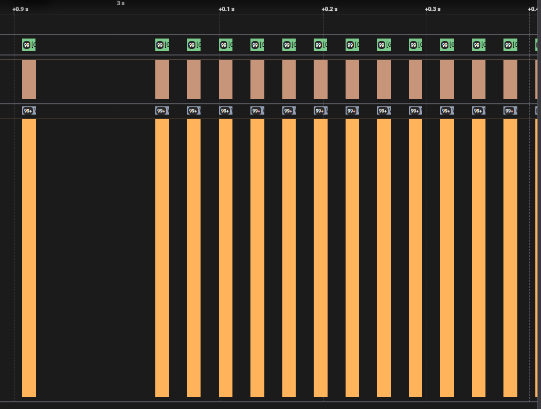 This is the measurement after pressing the button. Every little packet has lots of data, so you will get really disoriented if you don’t delimit it well. What i gathered from examining the structure of the packets :
- a 2-byte word,
0x80B0is sent before every packet - lots of
0xC0are being sent, maybe as a padding - only some are different from
0xC000
We can surmise that the data being sent is as words, since data is being repeated in a 2-byte fashion, and also every I2C transaction are sent 2 bytes.
Known-input sniffing
Next step is to see which bytes are the measurement, so let’s try measuring 1.111 meters. After some attempts, i got it to measure 1.111 meters. Let’s now measure more different values and make the difference between the packets. I measured at 0.352, 0.394 and 0.826 meters. What they all have in common is ‘0’ as the first digit.
After many attempts at manually seeing a difference, I resorted to Python, and I wrote a complicated code that does simple things, mainly taking all the data from a I2C packet, such as start + address + data[0] + data[1] + stop and concatenating only data[0] and data[1]. You can find the code on this repo. I made a csv file from all those exports of data and then differentiated them all together. Then, I did the same, but I added 1.111 meter measurement, so that I can see where the first digit is first used.
Sure enough, an anomaly came through, and we can read it at the 56th I2C ‘packet’.
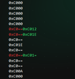
I tried comparing next the 0.352 and 0.394 measurements, to obtain the 3, knowing that 0xC012 and 0xC01E are ‘0’ at the first digit.
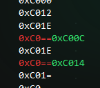
As we can see, 0xC012 and 0xC01E are right before these 2 new words, 0xC00C and 0xC01E. As it happens, 0xC01E was already ‘unfogged’, but nevertheless, we now know ‘3’. Or maybe not? When re-making another experiment, using another position for digit ‘3’, it gives us another code. This can be seen in a measurement such as 0.432 meters and 0.337 meters.
The code for ‘0’ remains 0xC012 and 0xC01E, but ‘3’ changes to 0xC004 and 0xC01E. The last word, 0xC01E remains the same, but the 4th bit is flipped for ‘3’. This could be from the decimal. I tried it again, but tested for ‘0’, as we already knew that the code for the first digit is 0xC012 and 0xC01E, and, what do you know, the code for .0 is 0xC01A.
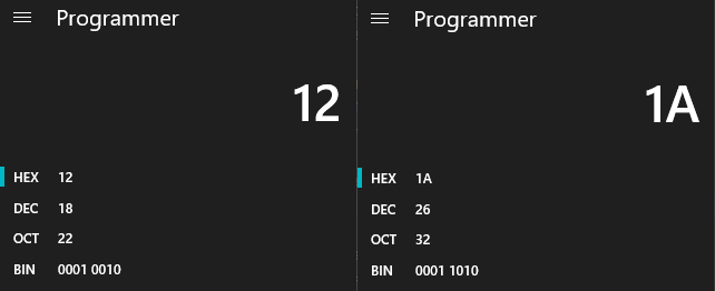
So, the first byte of the word is 0xC0 always, we can ignore that for now, but when talking about decimal dot digits, the 4th bit is flipped to ‘1’. After testing more, it’s the same for all of the digits.
This is the table of codes after I crunched many more measurements:
| Digit | Without Decimal | With Decimal Dot |
|---|---|---|
| 0 | 0xC012 0xC01E | 0xC01A 0xC01E |
| 1 | 0xC000 0xC006 | 0xC008 0xC016 |
| 2 | 0xC006 0xC01C | 0xC01E 0xC01C |
| 3 | 0xC004 0xC01E | 0xC01C 0xC01E |
| 4 | 0xC014 0xC006 | 0xC01C 0xC006 |
| 5 | 0xC014 0xC01A | 0xC01C 0xC01A |
| 6 | 0xC016 0xC01A | 0xC01E 0xC01A |
| 7 | 0xC000 0xC016 | 0xC008 0xC016 |
| 8 | 0xC016 0xC01E | 0xC01E 0xC01E |
| 9 | 0xC014 0xC01E | 0xC01C 0xC01E |
Moreover, we know that these values always appear at the position of 52nd I2C ‘packet’, meaning there are being sent 52 * 2 = 104 bytes of data before having the full picture of the measurement. Also, each full measurement cycle takes up 99 ‘packets’.
Keyboard emulation
One question remains, before trying to reuse the rangefinder. How do we start/stop it, and how do we action the measurement button, or the others? They don’t appear in the I2C packets when we press them, so how come?
If we go back to the recon phase, where we looked over the pins of the 20-pin ribbon cable connector, we can see that some pins go to the keyboard.
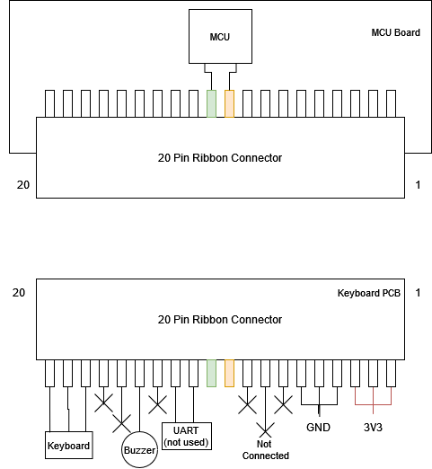
While this 3 wire connection might be worth pursuing, I didn’t go the mile and microsoldered wire to those small connectors, and I decided to just hack the keyboard and induce shorts digitally, instead of mechanically pushing the keyboard.
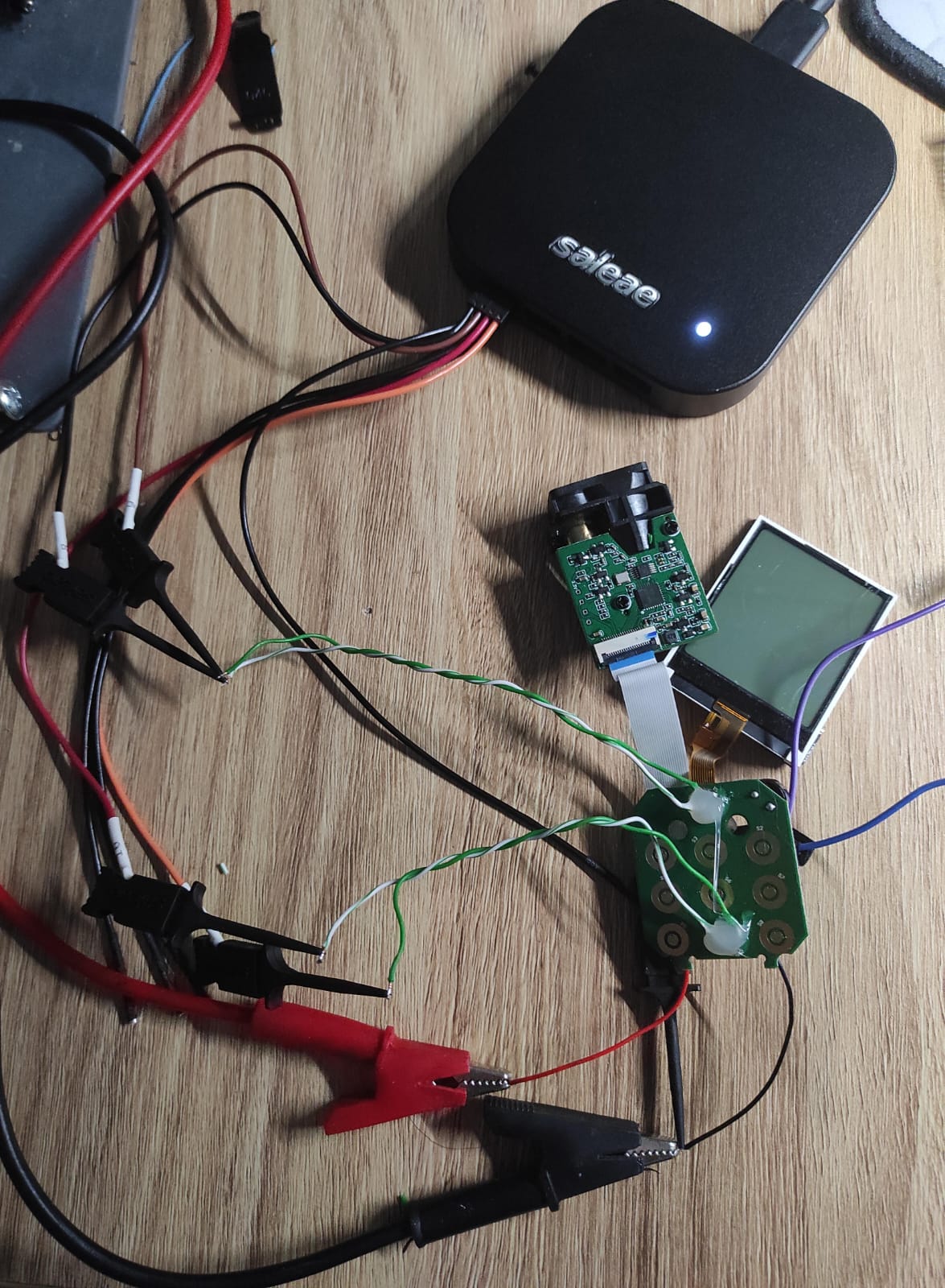
I want to see what kind of signals are transmitted over the line. We can’t expect for them to be a pure HIGH or LOW, so we need an oscilloscope to analyze this. Instead of bringing out a full scope, we can use the feature of the Logic Pro, where pins can be used as analog inputs.
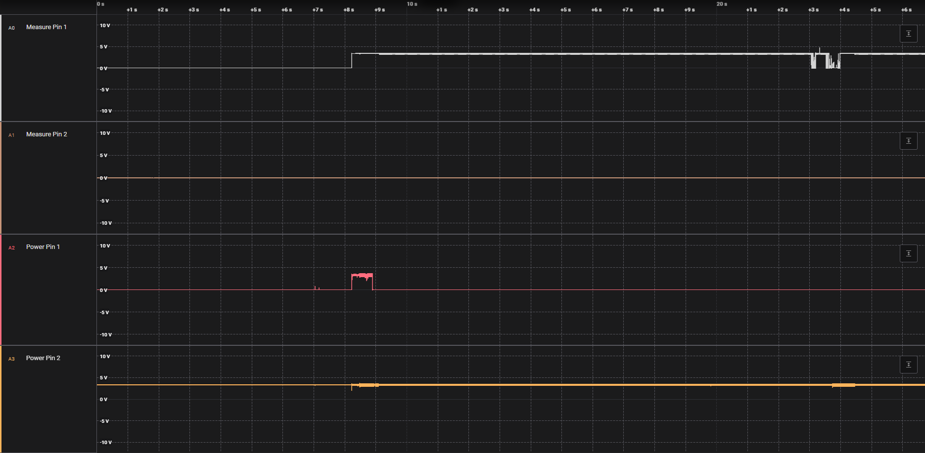
The first 2 traces are from the measurement key, and the last 2 are from the power key. The traces show that power key pin 1 should be pulled high to 3.3V to start the rangefinder. The measurement key pin 1 must be pulled low for it to take a measurement.