Don’t turn it on, take it apart
The next step in gathering the necessary tools for reversing, is to recon the insides of the rangefinder. Some commercial laser modules offer ready-to-use interfaces, such as UART RS-232, so we may take a shot at finding random 2-4 pins on the PCB, I’ll explain later why 2 or 4.
Take precautions
Don’t forget to take the necessary precautions when opening it, as you might never know what the engineers thought when assembling it. Some ribbon cables might tear, or you might destroy some parts on the PCB itself. Luckily, the plem 50 c3 is easily disassembled, it has only some philips self-tapping screws inside the plastic enclosure.
Next, try to take some photos of how this looked before you break something or forget how it was before.
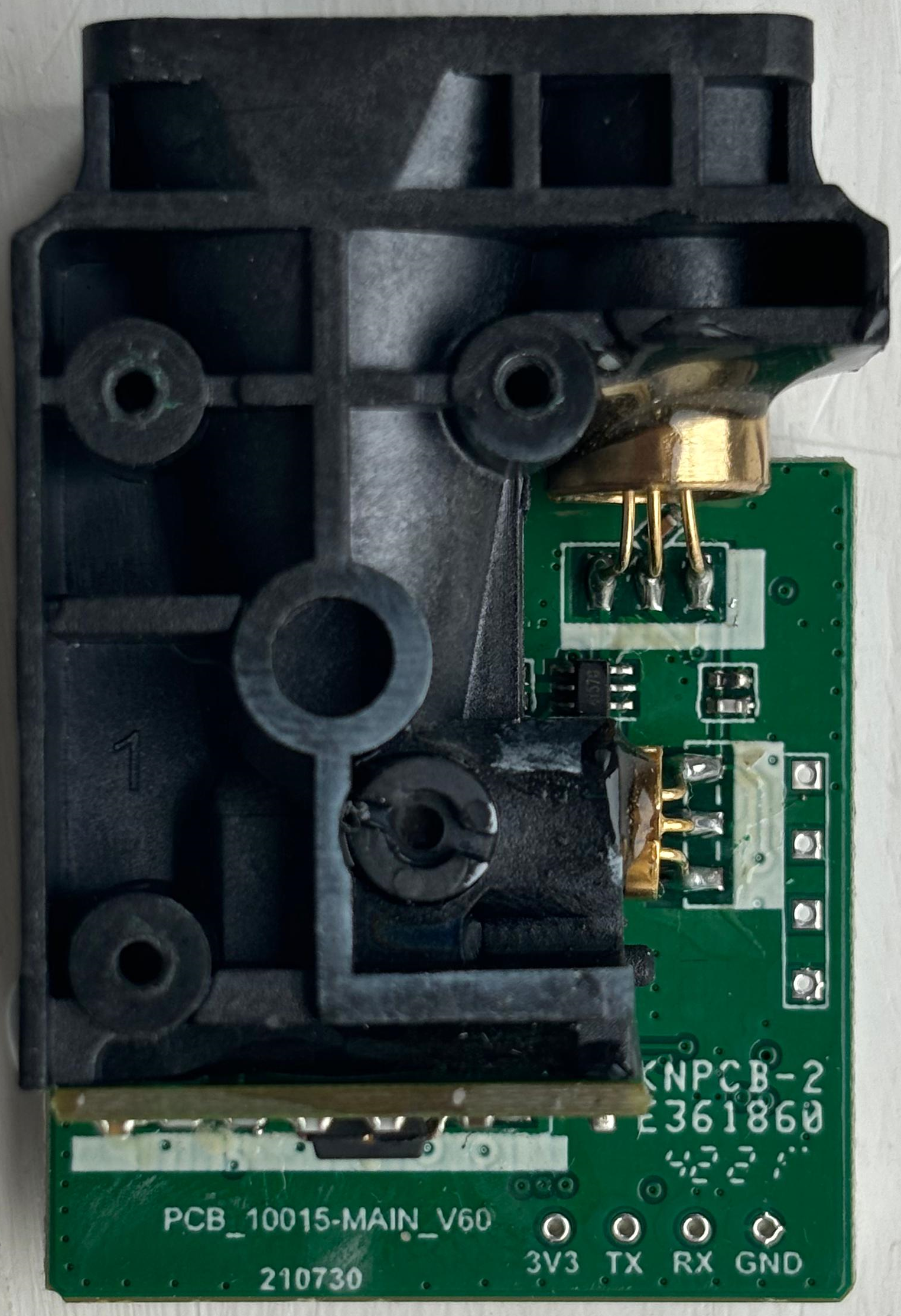
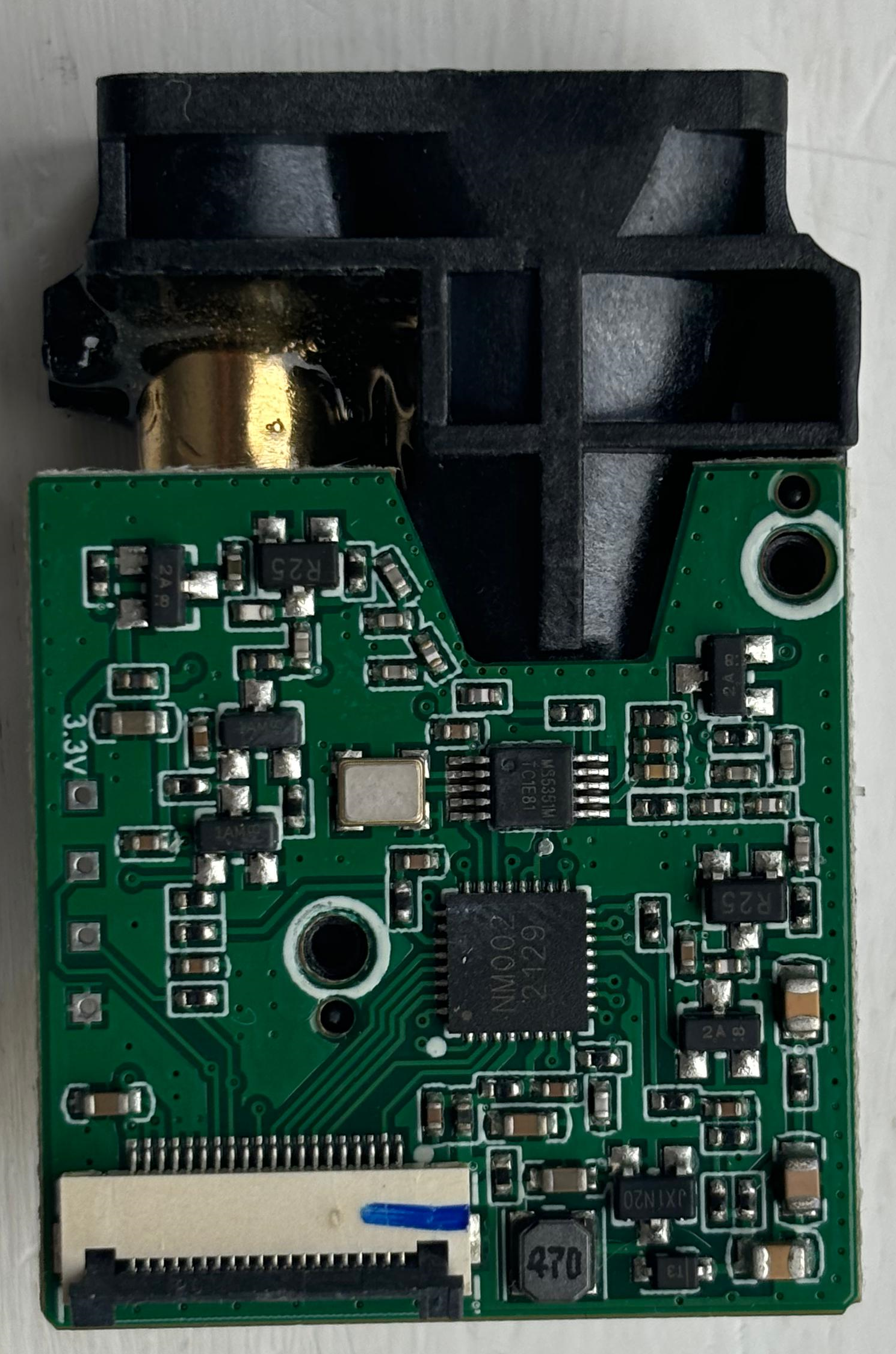
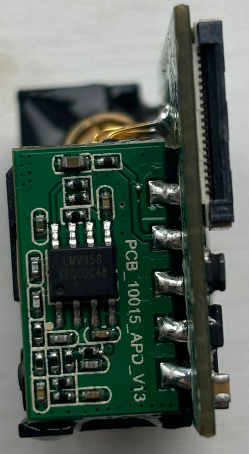
Laser module
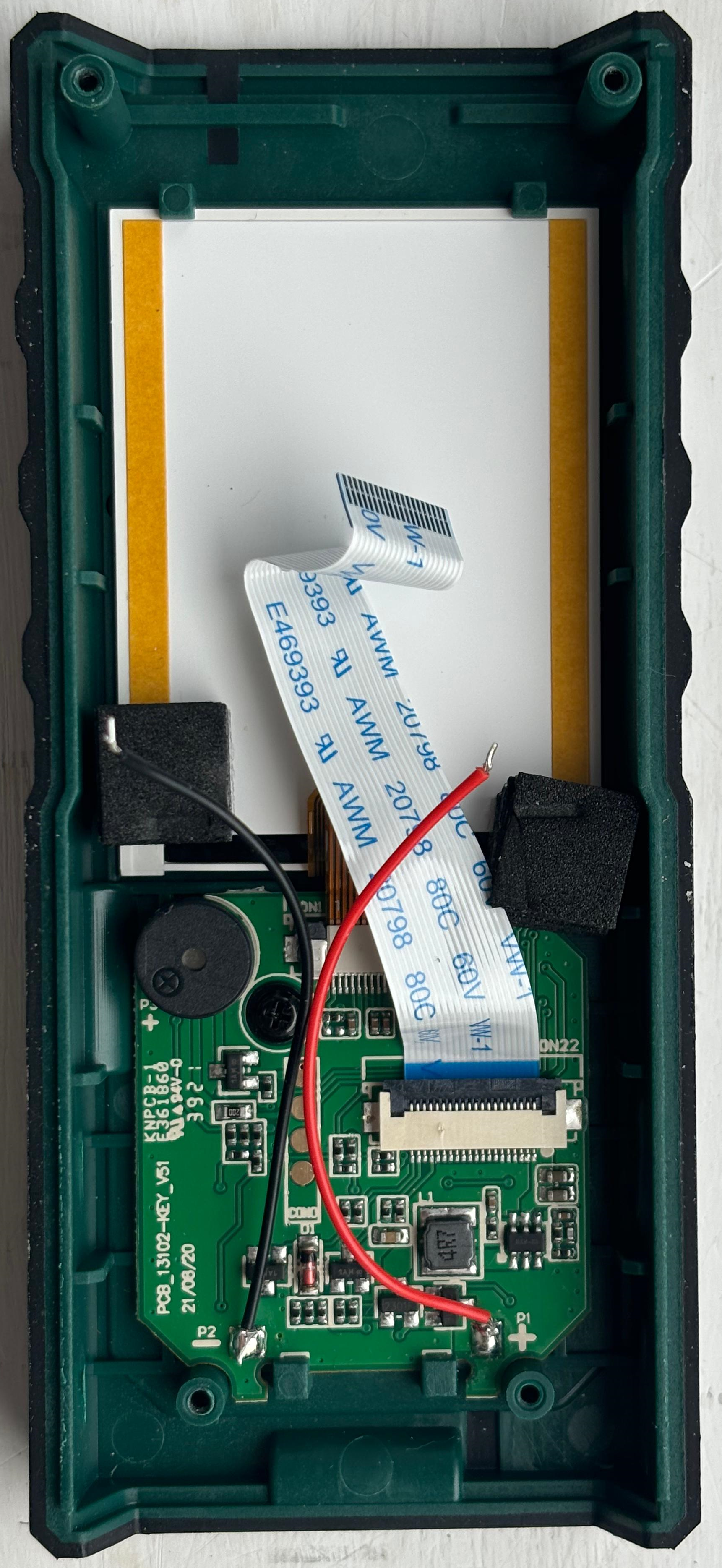
Keyboard and screen board
Make educated guesses
The main board looks like it doesn’t have a microcontroller, it has the keyboard, a buzzer, the screen and the voltage regulator circuit. The laser module might have it all encapsulated, with the microcontroller taking the data from the sensor, managing user input and sending data to the screen. This would mean that we are going to sniff the data lines from the microcontroller to the screen to have some relevant data.
As I said before, there are some ready-to-use modules that offer UART RS-232 interfaces. This interface needs 4 pins to achieve duplex communication, and is used for point-to-point communication between 2 devices, such as a microcontroller and peripheral. The keyboard PCB has 4 suspect pads, and the laser module has 2 unused connectors that have some damning pinouts. One of them is fully labelled with 3v3, TX, RX and GND, the standard for UART.
UART basics
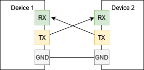
UART, also known as Universal Asynchronous Receiver/Transmitter, is used between 2 devices to communicate data in duplex. One listens on RX and the other transmits on TX. Look carefully, as the RX is always hooked up to the other’s TX pin, and vice-versa. GND is used as a common ground, and a 3V3 or 5V pin would be used to power the device directly through this connection.
UART uses a pre-established bit rate, called baudrate. This means that a device speaks at the same speed and the other will listen at the same rate, otherwise they won’t undertstand each other.
Now, as this becomes more clear, we can try sniffing data on those pins. The most reasonable thing to do would be to hook a USB-to-UART converter to a computer to decipher data, or use a logic analyzer. We will be using a logic analyzer, as it’s more versatile. The LA is used to read binary data off communication lines, and then with the help of software, to decipher it into data.
Testing UART
Before testing, I insert 3.3V inside the battery pins, the voltage regulator circuit will handle the surplus 0.3 volts.
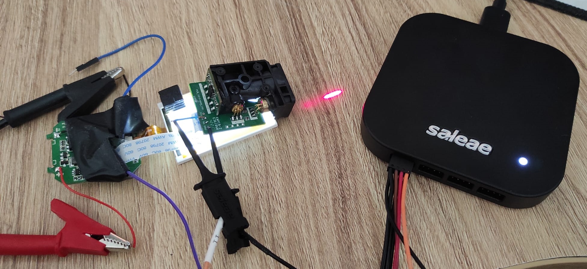
To test the UART, we’ll hook up a LA probe to the pins of the module, firstly trying with TX. We do this since we can’t be sure of all the other unmarked pins, so we may miss out.
We will use the Logic 2 software from Saleae, and the Logic Analyzer Logic Pro 16. You can find the download link for the software and the logic analyzer at https://www.saleae.com/. I endorse their products, as I really like the flexibility of the software - there are some really nice community extensions also.
The UART Setup
The UART Capture from all those suspect unused pins
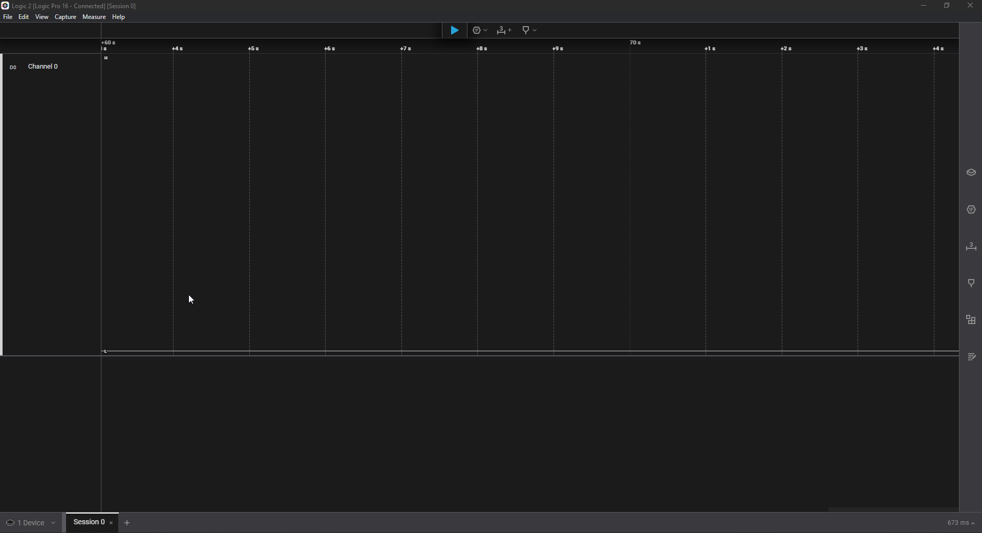
As you can see, the developers disabled this functionality, or maybe it wasn’t transmitting all along, we can’t know.
Bringing out the multimeter
If we cannot easily listen to an unused connection, the most logical thing to do would be to probe for other connections. As there are none, we must understand how the keyboard and screen talks to the microcontroller. Take out your multimeter, set it on continuity mode (beeping at a short-circuit mode) and disconnect the LA and power source before beggining to probe around. This can take out a while, but don’t be discouraged.
This is what I came up with after probing around with the multimeter.
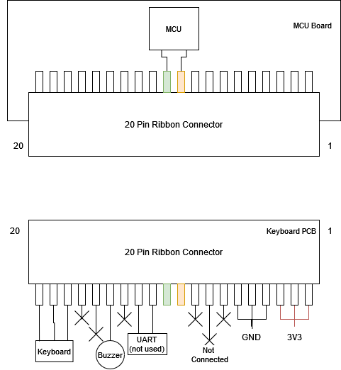 The pinout of the 20-pin connector has some unused pins, and some going to the keyboard, but right now, the interesting pins are the 2 that go inside the MCU, and that are also present at the ribbon cable of the screen. Let’s try to analyze it again.
 This looks like another popular protocol used in embedded devices for talking to peripherals, it’s I2C.
I2C Basics
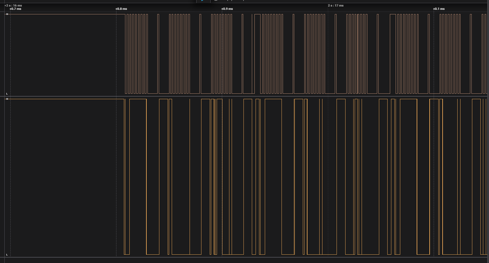
I2C or IIC comes from Inter-Integrated Circuit, and it’s a bit different to how UART works. I2C is a bus protocol, meaning there can be more than 2 devices on the line, waiting for data or pushing packets over it. The protocol uses 2 wires, one that is the clock (SCK), which synchronizes the data line (unlike UART, where every device sets the baudrate themselves) and the data line, where data is pushed in a high or low binary fashion (SDA). In the image above, the SCK is the signal above, and SDA is the signal below, since the one below is not the same everywhere.
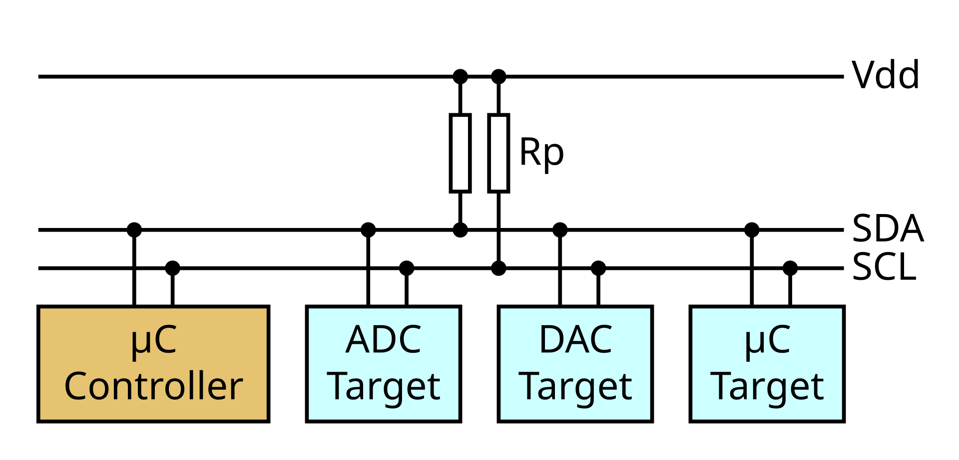 This is a typical I2C bus wiring, with one controller and some peripherals. Every device has an ID, or an address, in I2C terms. What you must know, is that the devices talking on the I2C bus first need to address the device before sending data, as it otherwise would be ambiguous.